1 / 4

| Parameter | Unit | PS 70E | PS 70I | PS 120B | PS 160D | PS 210V | PS 300V | PS 400V |
|---|---|---|---|---|---|---|---|---|
| Minimum mechanical failure load | kN | 70 | 70 | 120 | 160 | 210 | 300 | 400 |
| Minimum mechanical residual strength | kN | 56 | 56 | 96 | 128 | 168 | 240 | 320 |
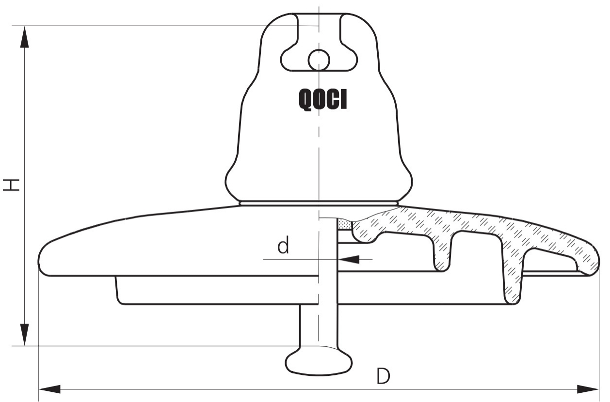
| Diameter (D) | mm | 255 | 255 | 255 | 280 | 290/300 | 320 | 360 |
| Construction height (H) | mm | 127 | 146 | 127 | 146/170 | 170/195 | 195 | 205 |
| Creepage distance | mm | 320 | 407 | 320 | 385 | 370/380 | 390 | 550 |
| Spherical connection (Ball-and-socket) | mm | 16 | 16 | 16 | 20 | 20 | 24 | 28 |
| Power frequency puncture voltage | kV | 130 | 130 | 130 | 130 | 130 | 130 | 130 |
| 50 Hz withstand voltage (dry) | kV | 70 | 72 | 70 | 72 | 72 | 82 | 90 |
| 50 Hz withstand voltage (wet) | kV | 40 | 42 | 40 | 45 | 45 | 50 | 55 |
| Dry lightning impulse withstand voltage | kV | 105 | 110 | 100 | 110 | 110 | 130 | 140 |
| Weight | kg | 3.6 | 4.3 | 3.9 | 6.13 | 7.2 | 10 | 16.2 |
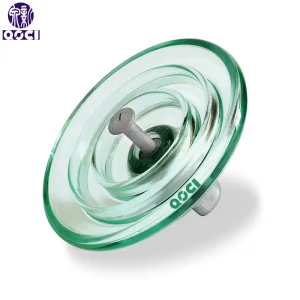
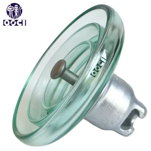
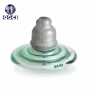
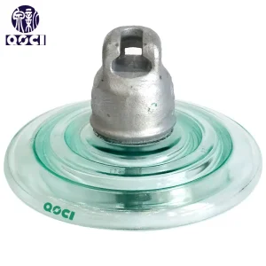
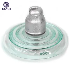
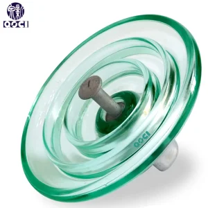
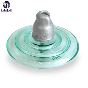
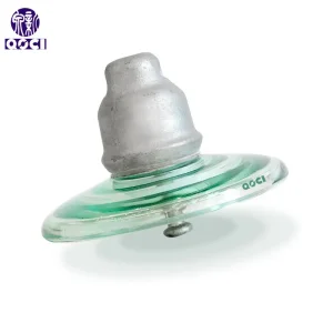
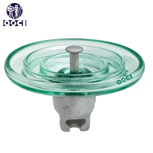
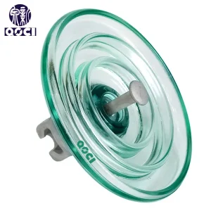
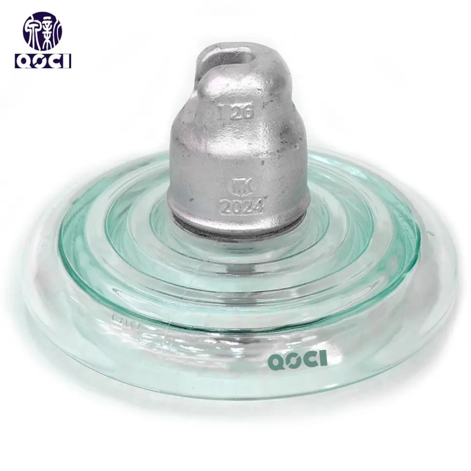
High-voltage transmission lines utilize strings of insulators connected in series in an articulated fashion. The quantity of insulators in the string is determined by the voltage class of the line, the construction of the supports, the type of insulator, and the operating conditions.
For lines at 35 kV, two PS insulators are typically installed in the string on wooden supports, and one or two additional ones on metal supports. The selection of the number of suspended insulators for 6-35 kV overhead lines is independent of the altitude above sea level. To avoid spontaneous detachment of the string, the rod is secured within the groove of the cap.
Note: Insulators PS-70, PS-70A, PS-70B, PS-70G, and PS-70D are now obsolete and are not produced. The modern standard designation is PS-70E.